Buy Suzuki Outboard Parts

Announcement

Collapse
No announcement yet.

My last electric problem-trim Wiring?

Collapse
X
 
  • Filter
  • Time
  • Show
Clear All
new posts

  • My last electric problem-trim Wiring?

    Okay, I pretty much have everything working on my 1984 Procraft fish and ski. My motor is 1984 Suzuki DT115. I bought it last year from a widow who know nothing about the boat.

    My only outstanding issue is the power trim switch doesn't work at the front of the boat. I works prefectly fine on the throttle. I traced the wire back from the front switch to just under the throttle control, to find out it wasn't even hooked up to anything....just wrapped up with electrical tape.

    I also discovered two wires coming out of the throttle control box with two plastic plugs capping off the two wires(brown and gray).


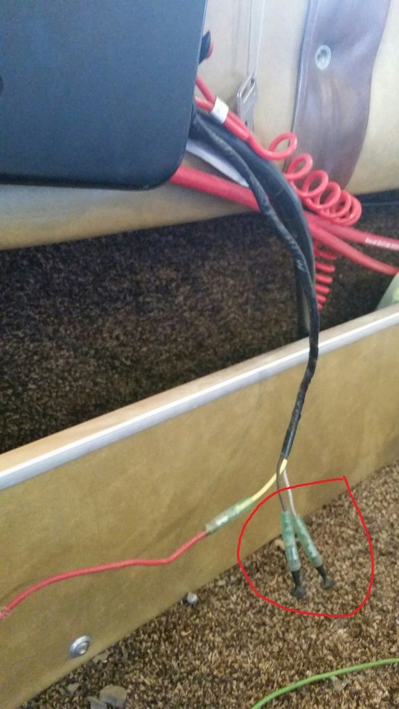
    Above shows two wires with female connector with plastic caps


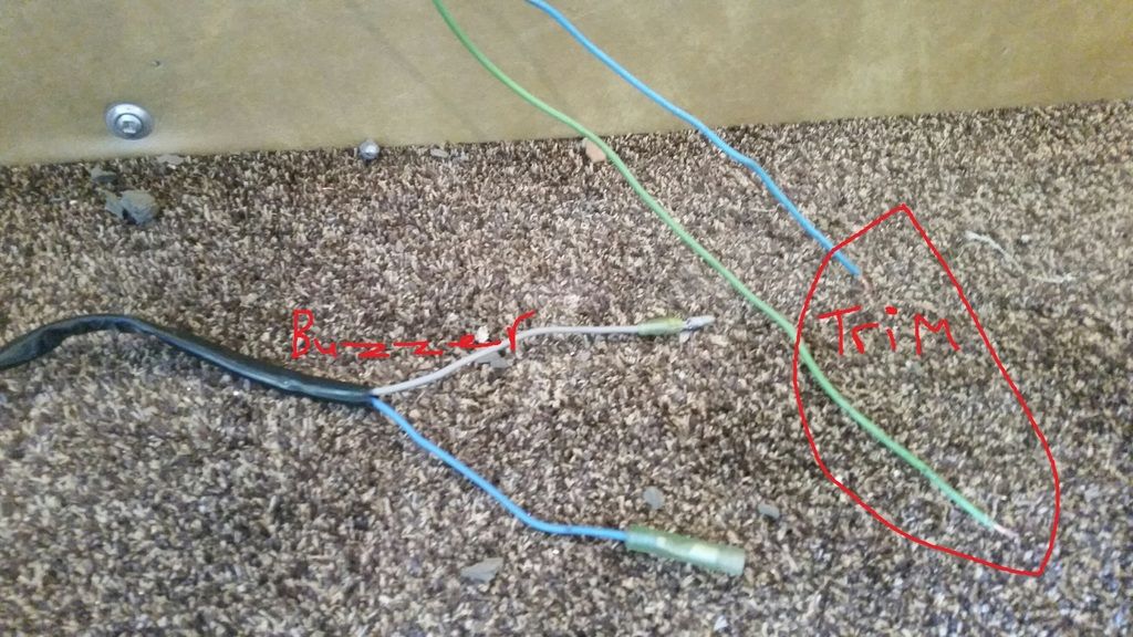
    I also found two more wires hooked up to a buzzer under the dash but not hooker up to anything. I thought maybe they go to the throttle control box. But the buzzer wires have one male and one female connector. The throttle wires are both female connectors with the plastic plugs.


    I don't know if this is warning buzzer. I know my buzzer was working last summer, because I heard it when I was trying to run down the old 2 cyle oil. It would buzz when I hit some big waves.

    Does anything have any ideas, on how the two trim wires need to be hooked up? It really doesn't need to be hooked up, but it's a sense of pride at this point....knowing everything is working.

    Thanks Shane
    Last edited by akareddog95; 03-29-2016, 07:52 PM.

  • #2
    Shane I just responded to your other question and then noticed this open item
    Is Your question relating only to the 'engine' trim function?
    You say the 'engine' trim on the remote (throttle) is working but the other power trim switch at the front is not working
    You are not referring to the switches designed to operate trim tabs?
    As far as those wires from the remote
    I would look up the manual for that remote an installation instructions I am sure you will discover the purpose of those two wires
    Art

    Comment


    • #3
      I don't have trim tabs on this old boat. If I want to use the trolling motor at the front of the boat. I can't pick up the DT115 motor with the front trim switch. The front trim switch isn't wired to anything.

      I just took a 2nd look at the manual and it says Trim gauge is standard equipment on the DT115. But, I dont have a trim gauge on this boat.

      I found a cleaner wiring diagram and I'll take another peak tomorrow.

      Thanks for your input and help!!!!

      Comment


      • #4
        Hi Shane

        Im a bit confused as to what you've got there!

        Normally there would be switches for the engine's PTT in 2 places: one on the side of the engine itself, and a second on the throttle/control box at the helm, or somewhere close by the key switch on the dash, depending on the boat's wiring setup.

        Is that what you've got, or is there a third switch for the PTT somewhere near the bow that is the one causing problems?? Or, is the problem switch the one on the control box/dash?

        Comment


        • #5


          Above is the picture of the front of the boat. The front bow switch labeled Trim up/down is the light blue ane green wires that I traced back that isn't hooked up to anything. This is 1984 DT115 so there is no trim switch on the motor or the transom.


          I have three sets of wires not hooked up to anything. My wiring diagram doesn't show any gray wires, but I have two of them. I assume that the trim wires or the buzzer needs to be hooked up to the set of wires that are capped off.

          The main wiring harness goes to the motor, but does anyone have any idea what the two capped off wires are for? Both have female connectors. The buzzer wire has one male and one female connector....so common sense rules it out from hooking it up to the two female capped wires.

          Thanks, Shane

          Comment


          • #6
            I did a little looking at older remotes and found that some had wiring to an emergency shut down switch that could be mounted on the dash with a lanyard attached at that point
            If you can find a part number for the remote you should be able to find a wiring diagram that is more specific

            Comment


            • #7
              Shane, if not mistaken, I believe there should be 3 wires from the front switch. I think they should be blue, pink and maybe green (blue, pink being the tilt up/down wires, and then green the common).

              I'm hoping this pdf file will be added, and help?

              Let us know? Good luck.
              Attached Files

              Comment


              • #8
                I have not been around a bass boats
                but.. would that trim switch be designed to trim out the small electric motor on the front of the boat vs trimming out the primary engine?
                Last edited by artdf175; 04-05-2016, 12:48 PM. Reason: correction

                Comment


                • #9
                  My Dad also has a 1984 Procraft with a Mecury engine. The front trim switch runs the 115 Merc.

                  Solarman, wouldn't the wiring colors be determined my the boat manufacturer on the front switch? There are three wires total.....green/red/blue.....Red is +. The switch is Montery On /off/Montery on.
                  Last edited by akareddog95; 04-05-2016, 10:33 PM.

                  Comment


                  • #10
                    Wire colors might be by manuf.?
                    The three wires from bow should be joined to the three from controller. Either switch should activate up or down trim on motor. It is just an additional switch.
                    Use an ohm meter, test which 2 wires have continuity when you press up. Then which 2 wires when pressing down. Your green is probably common, the blue up? The red/pink down?
                    Your controller should be wired like the wire chart I sent you.
                    The colored wires from your controller should match your wire harness to the motor.
                    Why is the red connected to white? Find the wires to the trim switch at the controller. Does the trim switch at controller work?
                    The white, gray, and black wires go to something else, maybe not used?

                    Good luck, post back.
                    Last edited by Solarman; 04-08-2016, 11:15 AM.

                    Comment


                    • #11
                      Ok this what I know.... The control Box is model number 3660-92E20

                      The front trim switch is wired like this:

                      Light Blue wire=momentary on
                      Red + hot wire= off
                      Green= Momentry on

                      There is no Neg wire on this switch, only three post switch....middle is hot.

                      Three wires coming out of the control box:

                      Yellow(looks White in picure)=goes to the Tach
                      Black= not hooked up
                      Gray= not hooked up

                      The Red wire is actual connected to a yellow wire and that goes to the Tach.

                      It appears the Suzuki control box has an internal warning buzzer built into the control box? I'm assuming the buzzer under the dash isn't hooked up because it isn't needed?

                      The ABYC chart shows Trim wires as Lt Blue and Green which matches my wiring on the front bow switch.

                      Solarman do still think the black and Gray wire is the trim up and down wires on the controller? Your chart says it should be Light blue and pink on the controller.

                      Thanks Shane

                      Thanks, Shane
                      Last edited by akareddog95; 04-11-2016, 11:16 PM.

                      Comment


                      • #12
                        Shane, you apparently need help with this wiring, otherwise you are going to short something out.
                        The white wire usually is hot if key is off/on, the gray wire should be hot if the key is in the on position. If the red wire is hot, and it goes to the trim switch it shouldn't be hot. What is the other end of the red wire connected to? ?
                        I cannot help you trace your wires out through the computer. If you cannot use a volt meter, and an ohm meter, you need to get help.
                        You have to have the proper wiring diagram for your motor and controls.

                        Good luck.

                        Comment


                        • #13
                          That's why I'm asking questions, I don't want to short anything out.

                          I have no troubles running a volt meter. I did test the wires last night coming of the controller. The black(-) wire and gray(+) wire when the switch is on. So I'm guessing they was never hooked up to anything and that's why it was capped off in the first place.

                          I'm starting to thing the front trim switch was never hooked up either? The front trim switch was piggy back off the hot side of another switch.

                          Thanks for all of your help.

                          Comment


                          • #14
                            Then look at the front trim switch. There should be a blue wire, at top, a red wire at bottom, and the green for common in middle? Is this correct? These three wires, if correct, should connect to the three wires at the control box, where they connect to the wire harness. They should be light blue, pink, and black.

                            Forget the gray and black wires. They are capped off and not used. If you add something that requires a switched wire, then you can use these wires.

                            Take a pic of wires at back of trim switch, and take a pic of the wires from control box where they connect to the wire harness.

                            Post back those pics.

                            Comment

                            Working...
                            X