
 Tweet
Tweet
Originally posted by Moonlighter
View Post
-
Yes, My 2016 DF140A was installed to the starter by my dealer. After I installed a C10 color gauge, it would give an alarm for a low voltage code. Thanks to Art, Moonlighter, and Tyler at IM; I have corrected this issue. I connected mine directly to the battery.Last edited by Nayna32; 01-24-2017, 10:56 PM.Henry -
Awesome I am glad everyone is good and taken care of. Grant does an unbelievable job to help people he has never met. He puts countless hours in and does it for zero in return. I appreciate it very much.
MikeComment
-
''''�t would not matter if there was battery voltage at the key constant, as long as it was fused, do you disconnect the battery in your car every night, no of coarse you don't. Up till 2005 all Suzuki ignition feed supply come from the battery pos cable at the starter,after 2005 the loom went from eight pin to sixteen and you had the option of connecting battery pos from the top of the loom or the bottom depending where your batteries were, obviously to help with voltage drop. As I said five years ago the reason you have to have batteries with enough cranking power to start a diesel, is the ecu has no built in software to account for voltage drop. In an automotive situation the ecm pcm has built in software to adjust for voltage drop eg, changing pulse width on the injectors and coil saturation, dwell in the ignition system and so on, so the engine will still start as low as eight volts. The computers in these engines wouldn't cost more than fifty dollars to produce.Originally posted by Moonlighter View PostComment
-
This sub battery cable you talk about, is this the White wire? Im just trying to learn. ThanksComment
-
Yes that is correct. The white wire is the Sub Battery cable.
MikeComment
-
Another point I meant to make yesterday, the white wire going to the ignition switch is only ignition feed, and when you turn the key on that battery voltage will travel back down the loom through a gray wire to the main power relay, coil to ground inside the ecu. This in turn will close the relay contacts and supply battery voltage to the ecu via pin 30 and your fuel pump, injectors, ignition and so on. The battery voltage that supplies the ecu with power comes via the starter motor battery pos terminal via a short red spade to a terminal block then through the sixty and thirty amp fuse. So all yo guys that want to fix your own electrical problems, you should have more than just a basic understanding electrical circuits, know how to check for voltage drops, have a wiring schematic and when you pull the cowl off don't just look for a white wire because white wires go to the voltage regulator ecu from the map sensor and so on.Comment
-
Question
I currently have a C-10 gauge and a Suzuki 200 AP with a Simrad NSS Evo2 installed with the Simrad Fuel Data Manger in my NMEA 2000 network.
When I disconnect it from the network I loose on my C-10 gauge and on my Simrad trip intel page my fuel level and fuel used since refill. Trip data is still there along with seasonal fuel used to date on the C-10 gauge.
I thought the Suzuki ECU kept all this data stored on the motor that's why I removed the Simrad Fuel Data manager in case there was some conflicts.
I was using the Simrad fuel manager as a backup for the Simrad only but seams without it I loose the data.
When I reconnect my Simrad Fuel Data Manager it returns see below. Any explanation would be welcome.
http://www.simrad-yachting.com/en-US...a-Manager.aspx
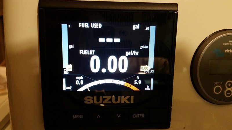
No Simrad Fuel Data Manager attached
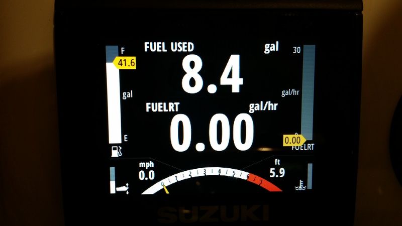
Simrad Fuel Data Manager Attached
 Last edited by Egretboy; 01-26-2017, 11:54 PM.
Comment
-
Originally posted by redlowrey View Post
Redlowery
question.. in following the white wire (Pos+) through the KEY. back to ECU.
From my understanding of the schematic -this is the power source for the ECU. The ECU does not power up until you turn the key to the on position.
When you turn the key to the 'start' position, it then will tell the ECU to throw the relay to the starter motor.
What am I misunderstanding here?
There have been some comments recently where the white wire gets it source of power.. either off the battery switch, and then in some cases off the pos(+) feed side to the starter motor that comes directly from the battery.
The later case can cause voltage drops to the ECU when the starter motor is activated, which I believe was the reason they changed the white wire power source to come directly off the battery.
I value your opinion and input, I just want to be correct in my assessment.
Thanks Art...Comment
-
Originally posted by Egretboy View PostSo after researching and reconfigure of the network without the Simrad Fuel Data Manager. The Suzuki C-10 Gauge will not keep Fuel level or Fuel Used or Seasonal Fuel in the gauge from the motor.Every module is seen in the network on the C-10 gauge. If there is some other setup or configuration I'm missing please shed some light on the subject on how this works in a stand alone setup with the Suzuki engine interface module and Fluid level sensor and C10 gauge and a 2016 200 AP in a step by step procedure It would be appreciated.Originally posted by Moonlighter View PostLast edited by Egretboy; 01-27-2017, 11:21 AM.Comment
-
http://www.suzukioutboardforum.com/s...mea2000-6.html
I saw on this close thread above alot of info similar to me. If there is a memory module built into the Suzuki Interface Module how come I can not get it to hold these settings? After taking out the Simrad Fuel Data Manager (aka EP85) I never did a auto detect of the network to see if anything was cleared from being corrupted by installing the SFDM. Should this be done to get the Fuel level working and Fuel used on the C-10 perhaps?Last edited by Egretboy; 01-27-2017, 12:17 PM.Comment
-
A lot was clarified by my dealer International Marine which has been a great service and hats off to there techs.
The auto configure is needed and the fluid level will need to be added to a separate page for fuel tank level.
I will report back once it done and reconfigured.Comment
-
I now think I am going blind from the small schematic this book has....Originally posted by redlowrey View Post
???different models different schematics???
Red.. you are mostly correct, again if I am reading my 150/175 correctly
I found the split on the white wire.. one side to the ignition key, the other to the 'coil' side of "ECM Main Relay".
The Gray wire comes off the "ON" key position side and terminates at the ECM. This is the 'power source' for the ECM.
The (+) power from the battery to the starter motor feeds back to the fuse box and first goes through the 60A fuse and on to the other 30A and 10A fuses in the box as power heads for the circuits those fuses protect. one 30A fuse is on the switch side of the starter motor relay, the other is on the switch side of the ECM relay.
So when the key is turned to the "ON" position, power through the gray wire powers up the EMC, in turn closing the EMC relay switch that subsequently powers up all the sensors.
Red, did I get it right?
thanks
ArtComment
-
That's right art from 2005 onwards the gray wire terminated at the main control relay, and the double spade meant when you turn the key on it powered up the ecu and the main control relay at the same time, that's why some of the change in the wiring loom happened, pre 2005 the gray wire powered up the main control relay then fed the ecu via pin 30 and every thing else. All the hoopla with the voltage drop on the white wire wasn't the fact that it came off the battery pos cable at the starter solenoid, it was how it was routed, via a short leader to a terminal block, then through the sixty and thirty amp fuse to the main control relay, from there a splice to feed the trim at the motor, then to a joint connector then to the ignition switch. So you can see why they changed it, but your power feed supply to the main control relay still comes off the bat pos at the starter, it makes sense that is where your main cable is going from off the battery.Comment
-
Red.. thank you...
ArtComment
-
Do you have a single engine with remote key switches. Does the second key switch need to have a separate feed for the white wire?Comment
Comment